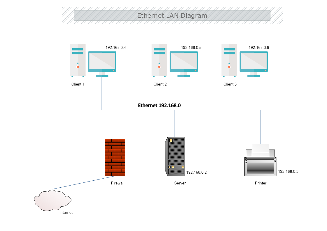
This is an Ethernet LAN Diagram that shows the connection between devices in a private network through a Bus Topology. The template is 100% customizable and you can edit every aspect of it with a few simple clicks in MyDraw.
What is an Ethernet LAN Diagram?
A LAN diagram's purpose is to present the arrangement of different components of LAN networks, and nodes, and show how these components are linked. The arrangement of the different nodes of a LAN diagram is referred to as topologies.
In this example, the network components are connected with a Bus topology.
What is Ethernet?
Ethernet is the traditional technology for linking devices through a wired local area network (LAN) or wide area network (WAN). The devices in the network communicate with each other via a protocol or common network language.
Ethernet describes how network devices format and transmit data so other devices on the same LAN, receive and process the information. Connected devices that use cables to access a geographically localized network -- instead of a wireless connection -- likely use Ethernet. From businesses to gamers, diverse end users rely on the benefits of Ethernet connectivity, which include reliability and security.
The Ethernet is typically less vulnerable to disruptions and can also offer higher security and control than a wireless technology. This makes it difficult for outsiders to access network data.
Why is Ethernet used?
Ethernet is used for its high speed, security, and reliability, especially for local networks used by specific organizations - such as company offices, school campuses, and hospitals.
Advantages and disadvantages of Ethernet
Advantages
- Low cost
- Backward compatibility
- Good data transfer quality and speed
- High speed and reliability
- Data security
Disadvantages
- For smaller and shorter distance networks
- Limited mobility
- The use of longer cables can cause incidents
- Doesn't work well with real-time or interactive applications
- Increased traffic decreases the speed
- Troubleshooting is hard when trying to trace which specific cable or node is causing the issue
Ethernet vs. Wi-Fi
Wi-Fi is the most popular type of network connection. Unlike wired connection types, such as Ethernet, it does not require a physical cable to be connected. Instead, data is transmitted through wireless signals.
How to create an Ethernet LAN diagram in MyDraw?
- Edit the ready-made template or Open a “Blank Drawing” file to create your own.
- From Library Gallery> Networking select the respective folder.
- From Library Gallery use the search library to find more networking shapes, suitable for your template.
- Once you have checked and marked the shapes they will be loaded on the left side of your drawing panel
- Drag and drop the shapes you would like to use into the drawing. Name the items in your network diagram.
- Use the connector tools to arrange your diagram. Draw connections between components.
- To add fill you can edit the Geometry Fill and Stroke from the Ribbon.
- In the Ribbon, you can select the Design tab to choose from a variety of shape styles and theme colors.
- Add a title and share your network diagram.
- Save the document in one of MyDraw’s native formats or export it in a preferred file format( PDF, SVG, EMF, VSDX, etc.).
- You can also export the document as a raster image.