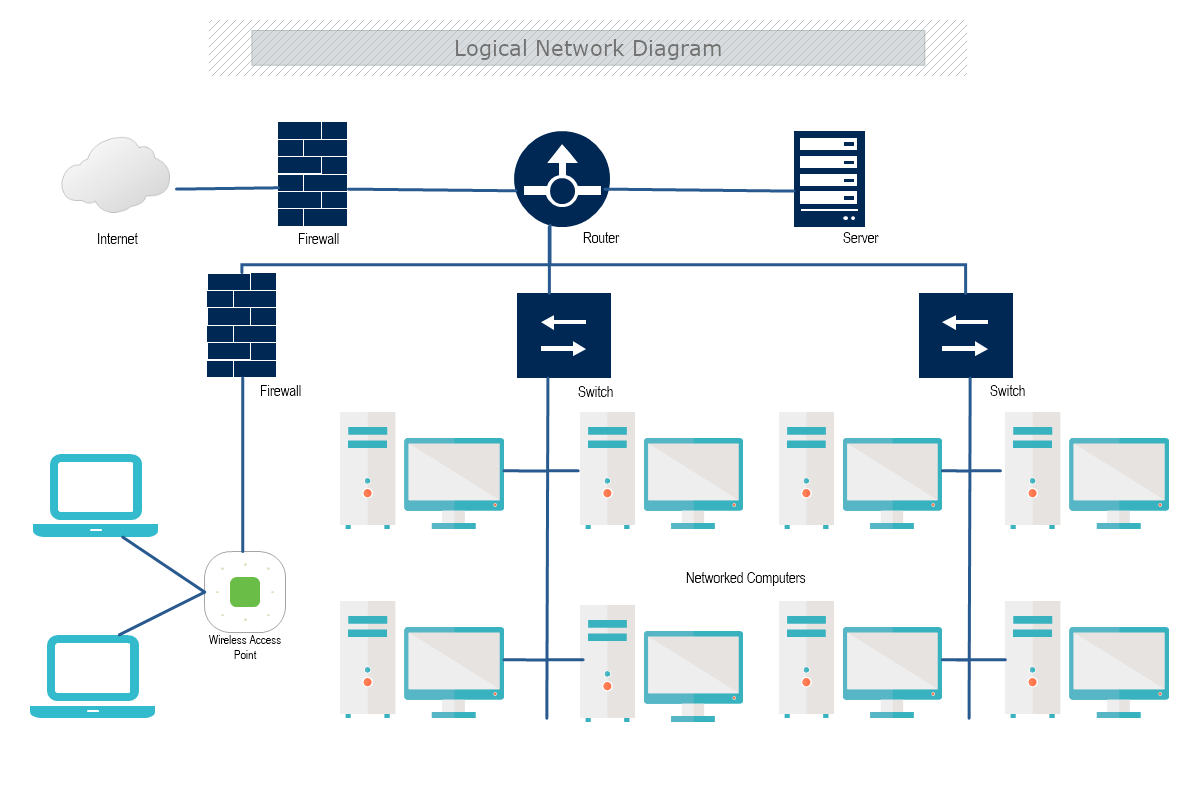
This is a Logical Network Diagram template that shows the flow of information and how the devices within the network interconnect. The template is 100% customizable and you can edit every aspect of it with a few simple clicks in MyDraw.
With a logical network diagram designed to display up/down status, admins can take a visual scan of the network, easily see where the problem is occurring, and even understand how it could impact-related nodes.
Both logical and physical network diagrams are key factors in effective network and IT infrastructure management. The network admins can troubleshoot and minimize downtime, plan for capacity, avoid disruption in the network, maintain software, and keep the connection between devices secure. One of the main types of network diagrams is logical.
Logical Network Diagrams
A logical network diagram presents how information in the network flows between components. The following elements should be included in your logical network topology:
- IP addresses, VLAN IDs, and subnet masks
- Routers and firewalls
- Routing protocols and domains
- Voice gateways
- Traffic flow
- Network segments
Use of Logical Network Diagrams
This type of network diagram is beneficial to management in terms of:
- Troubleshooting
- Firewalls
- Eliminate redundancies
- Planning
- Sharing network information
How to create a Logical Network Diagram?
It is best to map out the following logical elements: VLAN IDs, Subnets, Names/Labels, the Network address, and subnet mask, routers, VPN devices, and firewalls, DNS, IP -addresses, Logical interfaces, Routing protocols.
How to create a Logical Network Diagram in MyDraw?
- Edit the ready-made template or Open a “Blank Drawing” file to create your own.
- From Library Gallery> Networking select the respective folder.
- From Library Gallery use the search library to find more networking shapes, suitable for your template.
- Once you have checked and marked the shapes they will be loaded on the left side of your drawing panel.
- Drag and drop the shapes you would like to use into the drawing. Name the items in your network diagram.
- Use the connector tools to arrange your diagram. Draw connections between components.
- To add fill you can edit the Geometry Fill and Stroke from the Ribbon.
- In the Ribbon, you can select the Design tab to choose from a variety of shape styles and theme colors.
- Add a title and share your network diagram.
- Save the document in one of MyDraw’s native formats or export it in a preferred file format( PDF, SVG, EMF, VSDX, etc.).
- You can also export the document as a raster image.