Physical Network Diagram Template

This is a Physical Network Diagram template that shows the physical layout of the devices in the network. The template is 100% customizable and you can edit every aspect of it with a few simple clicks in MyDraw.

Download Template:
Nevron NDTX
Nevron PDF
Share:

Physical Network Diagram

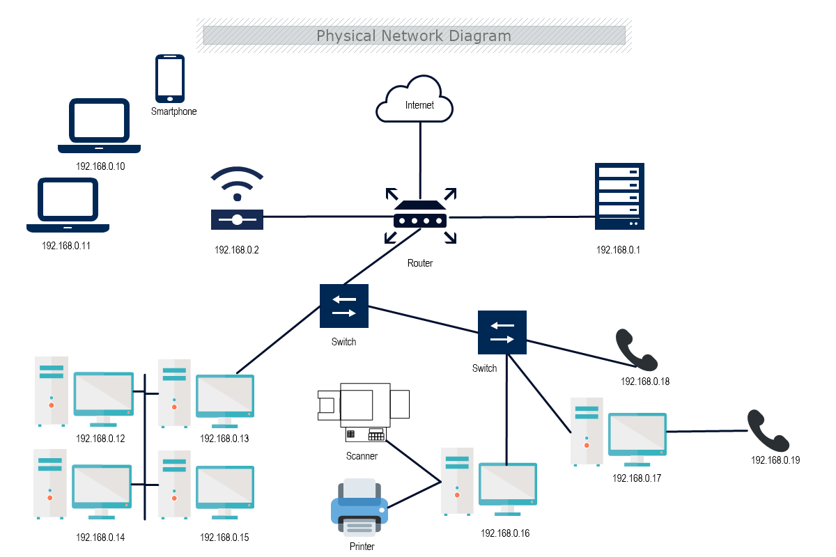
The Physical Network diagram outlines the physical parts of the network, like ports, cables, racks, and others. Whereas, the logical network diagram illustrates the invisible elements, connections, and information flow through the physical objects on the network.

What is the purpose of Physical Topology?

The media type to be used can be easily found in the topology. All the cables and media type is determined and the functions are better with the topology as it connects the network. This topology helps the system to function well as the network is connected.

The use of this topology reduces operational and maintenance costs. The utilization of resources and components has proven useful with the physical topology.

The importance of physical topology Network routing is done through network cables. The nodes have to be shared for the good establishment of the routes. In this type of topology, datasets are designed with better quality of control and also data integrity. Localization of errors is quicker and easily found. This data is managed better.

The relationships between the topologies are easily found and the features are shared with each type of topology. The optimization of one dataset updates the other ones. This is done through the synchronization of all datasets.

Due to the link between cables and features, the systems and devices are kept close to each other. The entire performance of the systems in the topology is run better due to the interconnection of the systems.

How to create a Physical Network Diagram in MyDraw?

  1. Edit the ready-made template or Open a “Blank Drawing” file to create your own.
  2. From Library Gallery> Networking select the respective folder. Other shapes can be found in the Library Gallery> ClipArt.
  3. From Library Gallery use the search library to find more networking shapes, suitable for your template.
  4. Once you have checked and marked the shapes they will be loaded on the left side of your drawing panel.
  5. Drag and drop the shapes you would like to use into the drawing. Name the items in your network diagram.
  6. Use the connector tools to arrange your diagram. Draw connections between components.
  7. To add fill you can edit the Geometry Fill and Stroke from the Ribbon.
  8. In the Ribbon, you can select the Design tab to choose from a variety of shape styles and theme colors.
  9. Add a title and share your network diagram.
  10. Save the document in one of MyDraw’s native formats or export it in a preferred file format( PDF, SVG, EMF, VSDX, etc.).
  11. You can also export the document as a raster image.