The circuit diagram (also known as an elementary diagram; electrical diagram; and electronic schematic) is generally a graphical representation of an electrical circuit. It visualizes the interaction between circuit components, by showing the actual electrical connections. Circuit diagrams visualize the physical arrangement of wires and the components that connect them within different electronic systems.
What are the circuit diagrams used for?
Circuit diagrams are used for illustrating different kinds of electrical circuits. Very similar to the network diagrams, the circuit diagrams are providing a visual representation of the schematic arrangement of all components and the wire relationships between them. This is very helpful when preparing a project for an electrical system that should be build or when trying to track down an issue in an already existing one.
Understanding circuit diagrams
As mentioned above, the circuit diagram visualizes electrical circuits. This is achieved by providing a schematic illustration where each component integrated into the electrical circuit is represented through an iconic symbol. For one to be able to read and understand the circuit diagrams, it is necessary to know what icon represents each component.
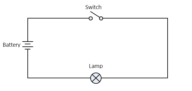
For example, a simple circuit diagram of an electric torch would look like:
To be able to read and understand this diagram it is necessary to be familiar with the symbols used in this example - battery, lamp, and switch.
Circuit Diagrams Symbols
All of the symbols used in circuit diagrams represent a specific electronic component. Over time, those symbols have been standardized internationally. See the full list of circuit symbols available in MyDraw
here.