EPC stands for Event-Driven Process Chain diagram and is used to visualize and plan business processes. It is essentially a flowchart-based diagram but there are some specific symbols used only in EPC. Although developed as part of the ARIS (Architecture of Integrated Information Systems), the EPC found far wider use in modern days. Its function is to help analyze and re-design business processes for achieving better productivity in multiple areas of business.
Understanding EPC diagrams
By definition, an EPC diagram starts with an event. This "event" may vary greatly based on business type, business model, department, etc. The shape which defines a process within an EPC diagram, however, is always the same: a hexagon. Some examples of events that could be the start of an EPC diagram are - a new order received, a loan application, a visit to a website, a booking request, etc.
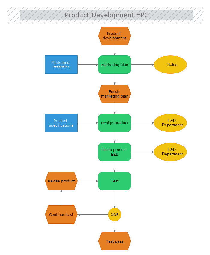
The steps from there and on will vary based on the process which is being analyzed. In the EPC diagram below, the event (Product Development) is followed by a process (the creation of a marketing plan). The "information material", i.e. Marketing Statistics is then stored and the plan pushed to the "organizational unit" Sales.
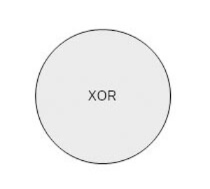
Very specific symbols for the EPC diagrams are the "AND", "OR, and "XOR" operators:
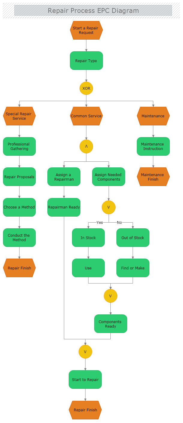
Their function is to clarify the flow within the diagram and is best explained via the example below. The example is triggered by an event, followed by the process. Then the XOR operator follows to activate either one of the paths. In this particular scenario, we have three paths so the choice will be amongst them. If there were 2, 4, 5 or any other number possible outcomes, however, the XOR operator will mean that only 1 of them can be activated.
When three processes are outgoing, or incoming to one
XOR operator, the logic is as follows:
- If all are false the operator cannot activate further processes;
- If all are true the operator cannot activate further processes;
- If two are true and only one false the operator cannot activate further processes;
- If one is true and the other ones are false then the following process is activated;
In our example, XOR activates the “Common Service” event. This event is followed by an AND operator.
An
AND operator marks the beginning and the end of a few paths via the following logic:
- If all are false the operator cannot activate further processes;
- If two are true and only one false the operator cannot activate further processes;
- If one is true and the other ones are false the operator cannot activate further processes;
- If all are true then the following process is activated;
Then the AND operator triggers both process paths. In our example, one of the paths leads to an OR operator. Like the AND operator we illustrate the OR operator on both ends of the process path that are determined by it.
An
OR operator marks the beginning and end of a few paths via the following logic:
- If two are true and only one false the following process is activated;
- If one is true and the other ones are false the following process is activated;
- If all are true the following process is activated;
- If all are false then the operator cannot activate further processes;
To find out more about the specific EPC Diagram shapes, please check out the link below.