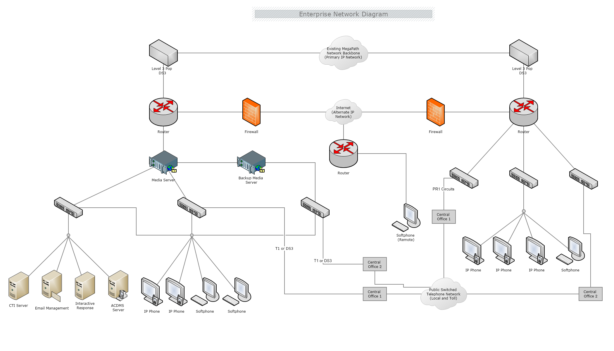
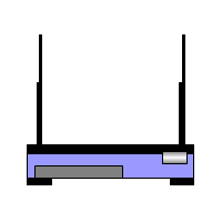
Network Diagrams are a visual presentation of a computer or telecommunications network, which can illustrate the activities and events of a project. They show the components that make up a network and how they interact, including routers, devices, hubs, and firewalls.
In general, a network diagram consists of a network that is made up of interconnected groups or systems. The scope of a simple network diagram can be either a single application, a family of applications, or even an entire enterprise. There are also other complicated network diagrams broadly designed to cover home networks, wireless networks, networking wirings, LAN networks, network topology, activity networks, and network cabling.
In the 21st century, most work is done via computers and machines. The large administration offices where people used to work mainly with paper-printed documents and written data are now replaced by digital libraries and laptops. Instead of having storage rooms, nowadays we have servers and virtual storage. Moreover, today people who work together as a team can be physically miles away from each other, yet that won’t be a problem. Their working machines can be connected to a computer network, allowing them to collaborate. This is where Network Diagrams come in handy. Whether large or small is the organization, there is always a need to visualize the connection between the servers and the computers, as well as the various access levels.
Network diagrams are divided into two types- logical and physical diagrams.
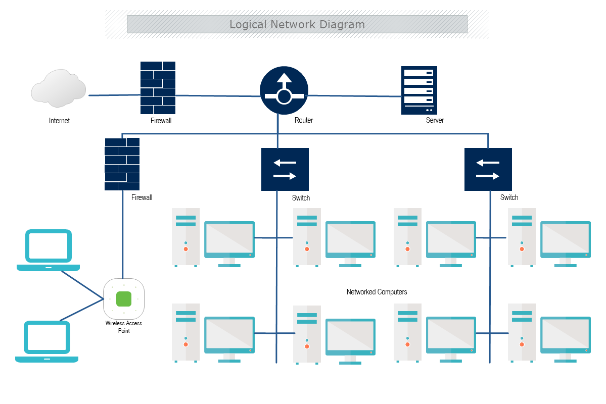
Logical network diagrams show the flow of information and how the devices within the network interact with each other. This also includes subnets, network objects and devices, routing protocols and domains, voice gateways, traffic flow, and network segments.
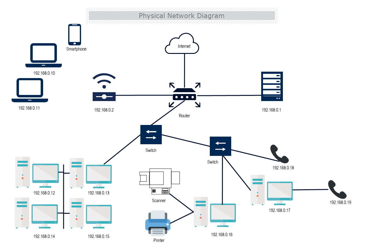
Physical network diagrams illustrate the physical arrangement/layout of the devices in the network. This type of diagram maps out the network architecture, including cabling, hardware, and ports.


Network diagrams are used in computer telecommunication to draw a graphical chart of a network. Every kind of network can be easily illustrated, showing clearly all users. This type of diagram is particularly useful for network engineers and designers in compiling detailed network documentation. Network diagrams also serve to show the exact type of connection they have with the rest of the machines in the network, as well as the data storage units.
Network Diagrams can also help when needed to detect an issue in the network hierarchy. By being able to see the exact topology of connections used for building the network and all the machines connected to it, one can track down the problem much easier.
With their capacity for showing how network components interact, network diagrams can serve a variety of purposes, including:
Network topology refers to the arrangement of elements within a network. Like network diagrams, network topologies can describe either the physical or logical aspects of a network. Logical topology is also known as signal topology.
Depending on the overall size and requirements, there are different network topologies. Each topology has benefits, suitable for different situations. It is highly important to choose the most effective since it can affect performance, stability, and other outcomes of the network.
Network management and monitoring require both the physical and logical topology of a network, to ensure efficiency and effectiveness of the connection. When it comes to networks there are several different main topologies which differ mainly by the manner of connecting:

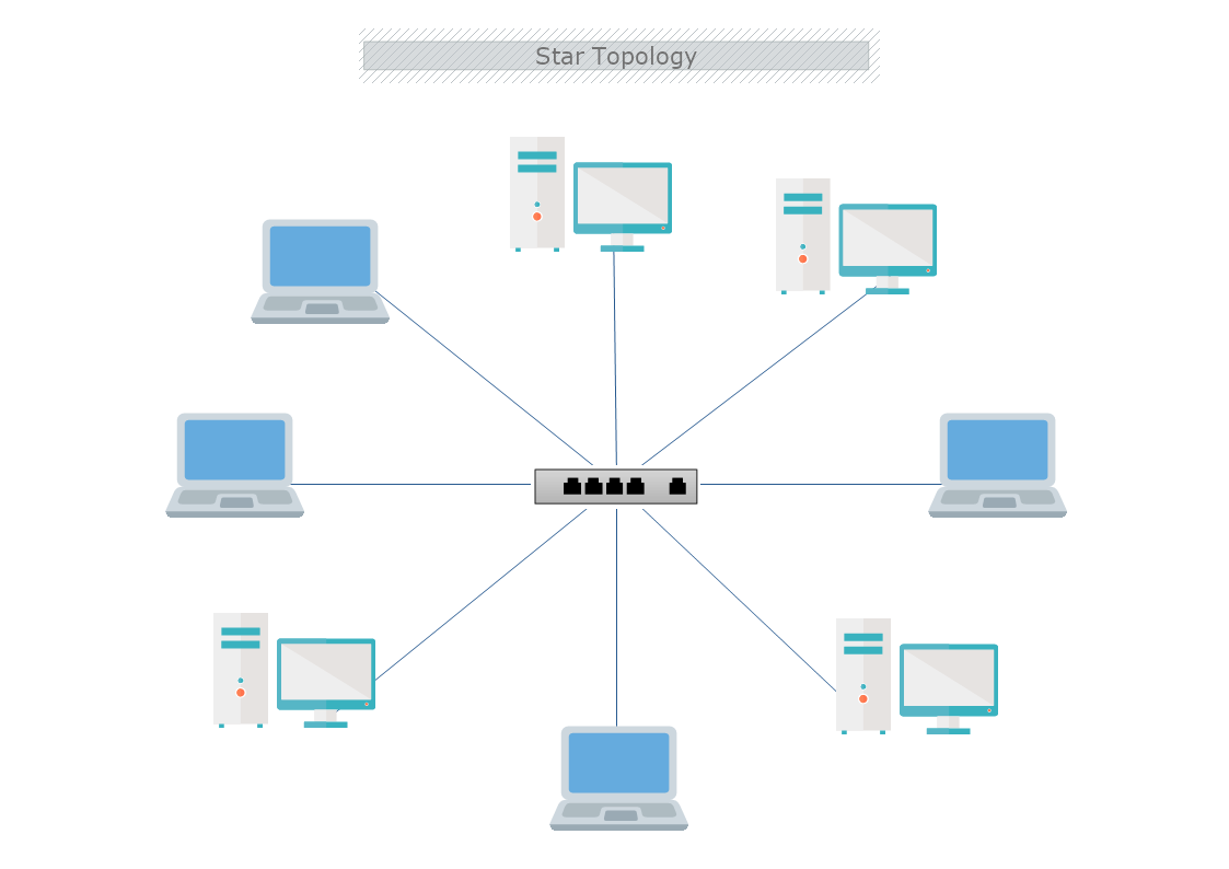
The Star Network is the most common network setups. In the star topology, every node connects to a central network device that may be a hub, switch, or router. The central network device acts as a server and the peripheral devices as clients. The connection to the center is made with Unshielded Twisted Pair (UTP) Ethernet.
Advantages of Star Topology
Disadvantages of Star Topology

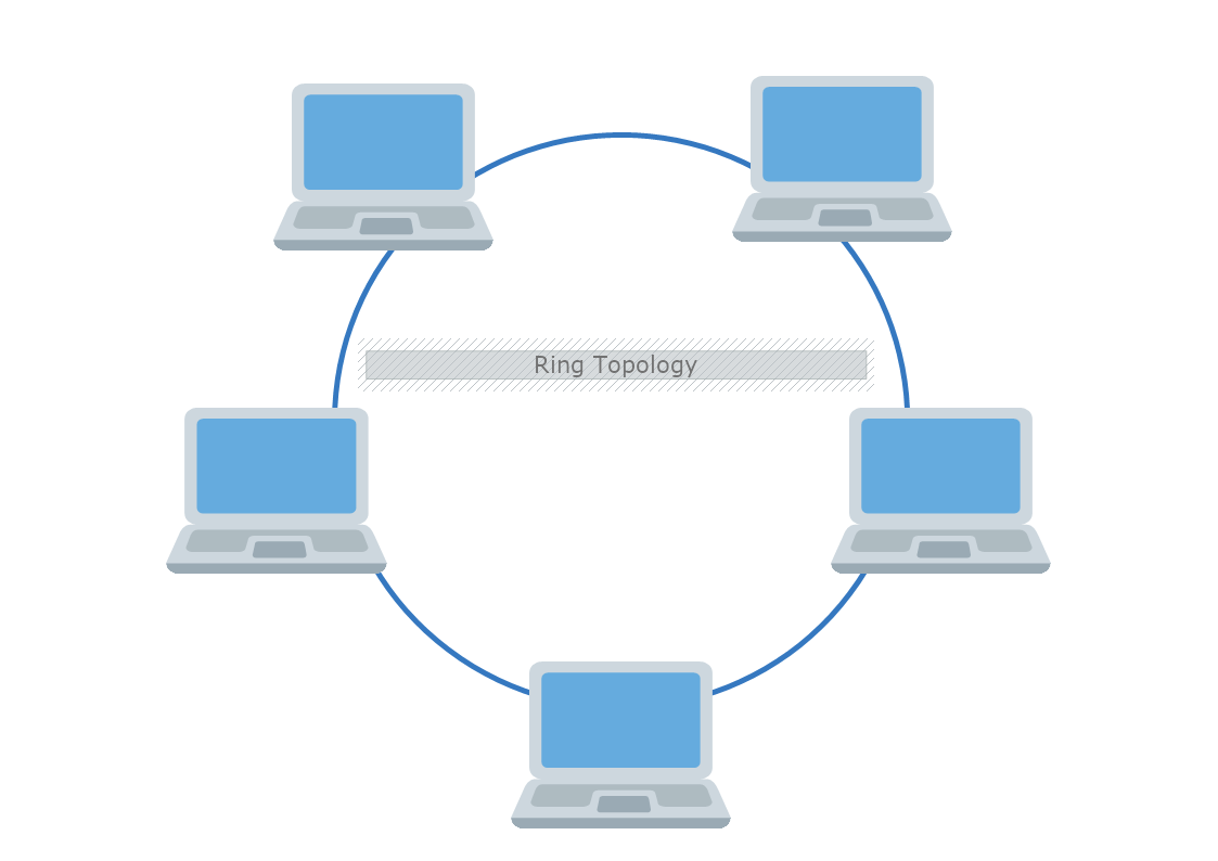
In a Ring Network, all nodes are connected in a circle path forming a closed loop. Each device has two neighbors. The data travels around the network either clockwise or counterclockwise( in one direction). The data is sent and received by a Token. Usually, this type of network is found in offices, small buildings, or schools.
Advantages of Ring Topology
Disadvantages of Ring Topology
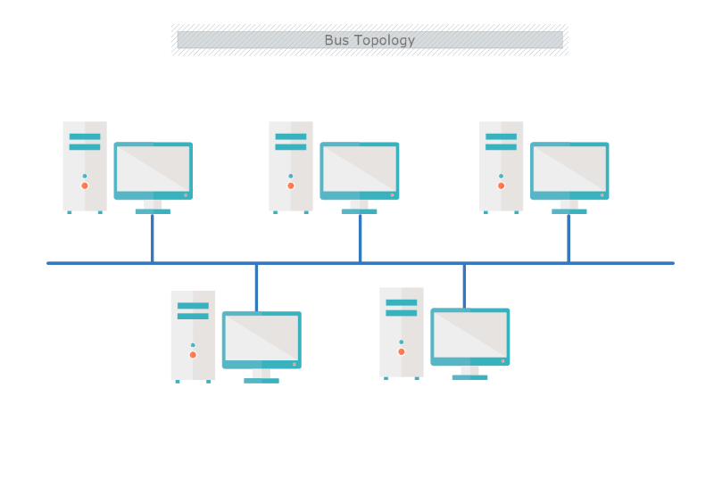
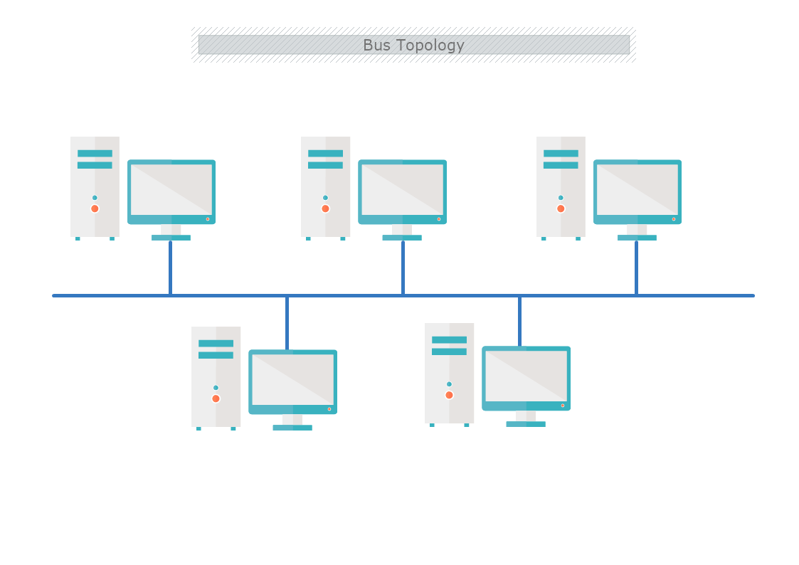
In a Line topology or Bus topology, all devices are connected to a single cable or backbone. At each end of the bus, there is a terminator, which absorbs the signal when it reaches the endpoint, preventing the signal bounce. The signal travels through the length of the cable in both directions from the sending computer. If a device communicates to another on the network, it sends a broadcast message onto the wire that all devices see. However, only the intended recipient accepts and processes the message. Bus topology differentiates by having all nodes connected through a central medium and it is easy to install.
Advantages of Bus Topology
Disadvantages of Bus Topology
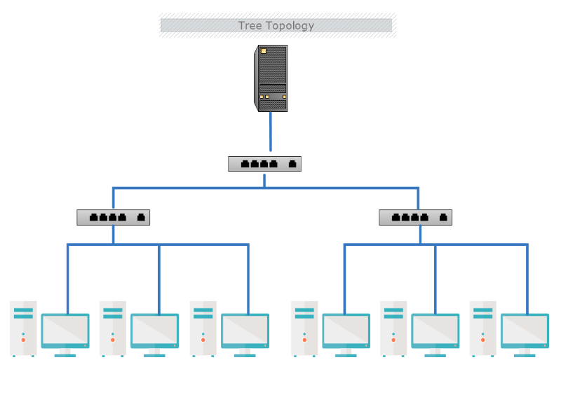
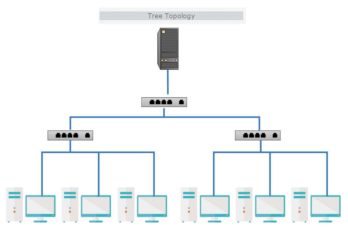
Tree topology is a combination of multiple star topology onto a bus. In this configuration, nodes of the underlying bus network topology are replaced with a complete star topology. The hub is connected directly to the tree bus, allowing each hub to function as the root of a tree of devices.
Advantages of Tree Topology
Disadvantages of Tree Topology
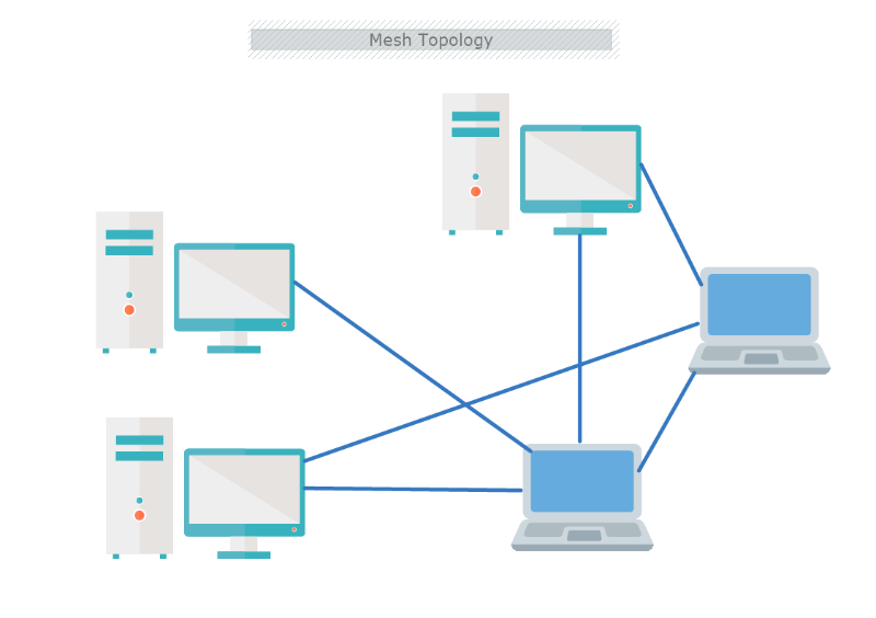
Mesh topology has multiple connections, as all computers and network components are interconnected directly with each other. It is the most fault-tolerant network topology. Like their traditional WAN counterparts, meshed VPN topologies can be implemented in a fully or partially meshed configuration. In the full meshed configuration there is a large number of alternate paths to any given destination. Also, fully meshed configurations have exceptional redundancy, as all VPN devices provide a connection to one another. In the partial-mesh topology, all the links are connected in a more limited fashion to other links.
Advantages of Mesh Topology
Disadvantages of Mesh Topology
A network diagram is a unique kind of cluster diagram that represents a wider or smaller structure of computers or other networking devices. For this reason, preidentified icons or symbols are used to draw network appliances and the style of lines between two nodes that describe the type of connection.


In MyDraw shapes library, you will also find a set of symbols from the leading cloud hosting services- Invalid Page Link. Page with ID:lf_shape-libraries_networking_cisco does not exist.Cisco and Invalid Page Link. Page with ID:lf_shape-libraries_networking_net-equip does not exist.NetEquip (also Invalid Page Link. Page with ID:lf_shape-libraries_cloud_amazon-web-services does not exist.Amazon Web Services, Invalid Page Link. Page with ID:lf_shape-libraries_cloud_azure does not exist.Azure, Invalid Page Link. Page with ID:lf_shape-libraries_cloud_google-cloud does not exist.Google Cloud, etc.). For a more comprehensive list, see our full Network diagram shapes page .